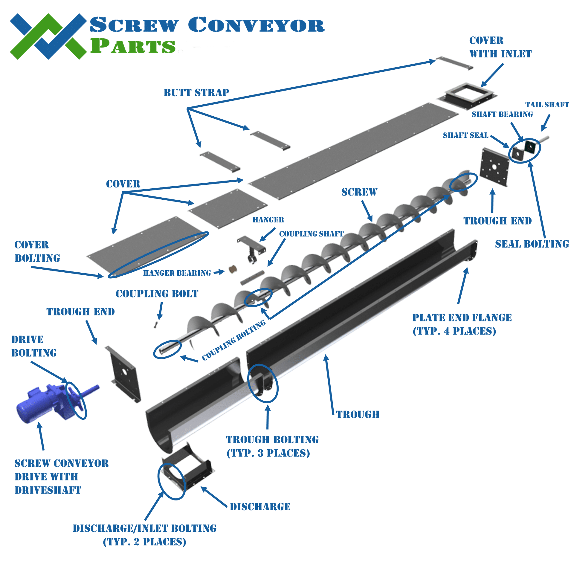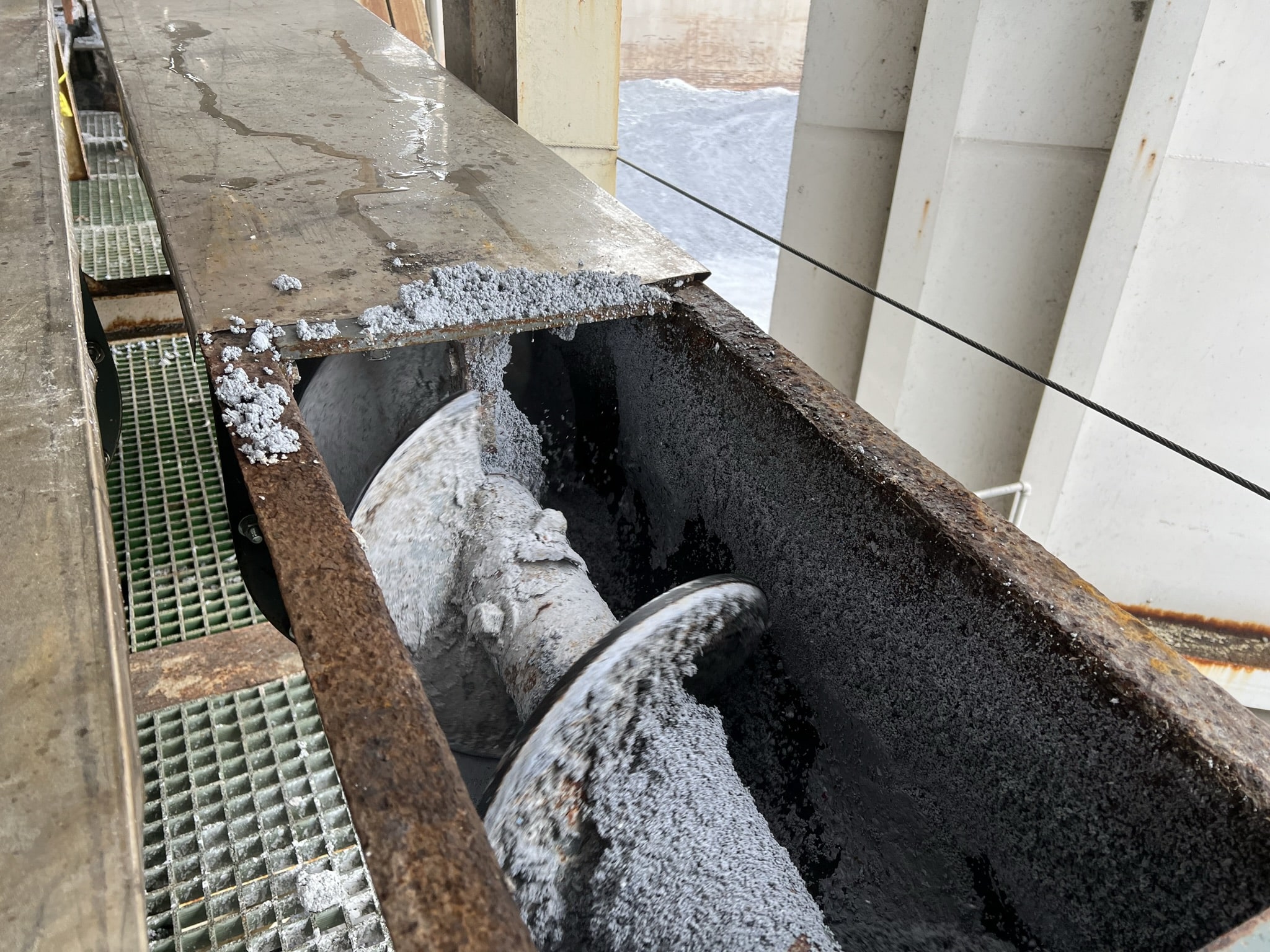
Sizing a screw conveyor can be very easy, when you know a few of the basics. Of course, there are many screw conveyor applications which add elements to the calculation set that require some experience and expertise but for most traditional applications the process is well defined and resources are available in every screw conveyor manufacturer’s catalog. The basics of sizing a screw conveyor are to know what you know about the application. The material being conveyed, the length, the incline and the amount being conveyed are all required to size a basic screw conveyor. We should note there when we say screw conveyor we mean a conveyor and not a feeder. A feeder is a screw conveyor with the inlet flooded; like under a bin, hopper or silo. In a feeder you have to account for the flooded inlet in the calculation. A screw feeder involves a few more variables such as variable pitch, increased friction from the material being fed and accounting for the weight of the material over the screw at the inlet. A screw feeder calculation is much more complicated than a screw conveyor calculation and unfortunately no one publishes detailed calc sets for feeders. This will be a subject of a future write up on Screw Conveyor Parts.com or email us and we will help.
There are some things you need to know about most screw conveyor calculation sets that may not be specifically discussed in most screw conveyor manufacturer’s catalogs. The following special cases need to be addressed in more detail than a simple conveyor calc set can provide and are typically where a more seasoned screw conveyor designer is engaged. In a later article we will provide some more detail on each one of these special cases.
- Incline and decline screw conveyors
- Screw feeders
- High (200°F+) and low temperature (40°F-) material
- Highly abrasive materials like sand, clinker and aggregate
- Large materials (+2″)
- Very small materials (Cement, Flour, etc…)
- Food and sanitary applications
- Stainless steel and special alloys
- Corrosive materials
- Stringy materials (Shredded paper, ribbons, etc…)
- Sticky materials
- Very wet materials (Sludge, water, etc….)
- Many other unique applications
Note: The information below is merely an outline of screw conveyor calculations. For more details, charts and examples refer to screw conveyor manufacturer’s catalogs here, such as KWS, Thomas or Martin.
Diameter and RPM:
The first step in sizing a screw conveyor is to determine the diameter. The diameter is a function of the rate of the conveyed material, its density, trough fill level, screw pitch and speed of the screw. To ease the calculation, most screw conveyors are full pitch, meaning the distance from flight to flight is the same as the diameter, and are running at 30%-45% trough fill level. Trough fill level is the percentage of available cross sectional area of the screw diameter. Why 30%-45% trough loading? The answer is the material needs some room to move around as it is conveyed and more importantly, it allows the material to flow under any potential hanger bearings. The recommended trough loading for each material can be determined from the material chart in the beginning of any manufacturer’s catalog. Typically, 15% is used for abrasive materials, 30A is used as a default, 30B is slightly higher speeds of 30A and used for easily flowing materials, 45% is used for very free-flowing and uniformly sized materials and 95% is used for feeders.
A diameter will have to be assumed to start the calculation and then the speed at that diameter calculated. The speed should be under the published maximum speed (RPM) but in most cases 40RPM – 80RPM is a good range. There are published max speeds for different diameter screw conveyors but these speeds tend to be much higher than is recommended for a long and reliable screw conveyor service for almost all applications except feed and grain. Using a speed of about 2/3rds the published maximum RPM will help reduce the wear on your screw conveyor and increase the overall like of this asset.
Example:
Product: Paper Pulp
Rate: 13,00 Pounds per Hour (PPH)
Density: 62 Pounds per Cubic Foot (PCF)
Fill Level: 30%
Distance: 30ft
Incline: Horizontal
Inlet Type: Control Fed (From another conveyor or feeder)
Step 1:
Assume a Diameter, Pitch and Pipe Size
Assume 9″ Diameter, 9″ Pitch and 2 1/2″ Pipe OD for a 2″ Driveshaft with a 2 7/8″ OD
Step 2:
Calculate RPM
RPM = r / p / (π x ( D² – d² ) x P x K x 60 / 6912)
Where:
r = Mass Flow Rate = 13,000 PPH
p = Density = 62 PCF
D = Screw Conveyor Diameter = 9in
d = Pipe OD = 2.875in
P = Pitch = 9in
K = % Loading = 30%
RPM = 39.2, so lets go with 40RPM.
Horsepower (HP):
After the diameter and RPM of the screw conveyor are known the motor horse power (HP) has to be determined. The HP is the force required to move the product over the length of the conveyor in a given amount of time. Since screw conveyors tend to tumble material, this calculation also has to account for this tumbling of the material while it is moving along the screw conveyor. Most screw conveyor manufacturers call this the “diameter factor”.
The basic HP calculation set for screw conveyors has three parts. The HP to convey the material, the HP to turn the screw, by itself, and the combination of these two for the total required HP. The calculation set includes the Hanger Bearing Factor to account for the friction of the hanger bearing and the material factor which accounts for the varying frictional properties of different materials. As stated above, these calculations work well as long as you stay within the parameters of trough loading and speed.
Example:
Carrying over from the above example
Step 3:
Look-up Material Factor, Diameter Factor and Bearing Factor
Fm = Material Factor = 1.50 (See material chart per CEMA)
Fd = Diameter Factor = 33 (See Chart Below)
Fb = Bearing Factor = 2.00 (See Chart Below)
Step 4:
Calculate Frictional HP
HPf = L x RPM x Fd x Fb / 1,000,000
Where:
L = Conveyor Length = 30ft
RPM = Speed = 40 RPM
HPf = 0.079
Step 5:
Calculate Material Factor
HPm = r x L x Fm / 1,000,000
HPm = 0.585
Step 6:
Calculate Total HP
HPt = (HPf + HPm) x Fo / e
Where:
Fo = Overload Factor. If HPf + HPm <5, use the overload table below. If > 5, use 1.00 = Approx. 2.35 (See Chart Below)
e = Combined Motor and Gearbox Efficiency = Assume 0.85
HPt = 1.84, so lets use 2HP or 3HP
Component Size:
The last step is to determine the shaft size, coupling bolt diameter, pipe size and pipe schedule. Most manufacturer’s catalogs will give some basic selection criteria for standard carbon and stainless steel components. Once you get into longer than standard length applications the calculations require a little more engineering to get the right answer. To size these components one can use the largest available shaft size for the particular screw conveyor diameter, run detailed stress calculations or use some of the charts available in some manufacturer’s catalogs.
The fighting thickness, trough thickness, trough end selection, seal selection and various other selections are dependent on the application and are usually more dependent on the abrasiveness and willingness to spend money than any well-defined calculation set.
In conclusion, sizing a basic, standard length, horizontal screw conveyor can be very straight forward. The expertise of a company like Screw Conveyor Parts.com comes into play when your veer into applications less well defined. If you require some assistance sizing your screw conveyor simply email us and we will help guide you through the process and fill in any of the missing data you need to ensure the screw conveyor you buy meets your needs now and long into the future, just click here and fill in the form.
Diameter Factor
| (D) | Fd |
| 6 | 18 |
| 9 | 31 |
| 10 | 37 |
| 12 | 55 |
| 14 | 78 |
| 16 | 106 |
| 18 | 135 |
| 20 | 165 |
| 24 | 235 |
Bearing Factor
| Bearing Type | Fb |
| Ball, Roller or None | 1.0 |
| Bronze, Wood | 1.7 |
| Plastic, Nylon, Teflon, UHMW | 2 |
| Hard Iron, Stellite | 4.4 |
Overload Factor
| HPm+HPf | HPo |
| 0.5 | 2.47 |
| 1 | 2.03 |
| 1.5 | 1.78 |
| 2 | 1.6 |
| 2.5 | 1.46 |
| 3 | 1.34 |
| 3.5 | 1.24 |
| 4 | 1.16 |
| 4.5 | 1.09 |
| 5 | 1.02 |