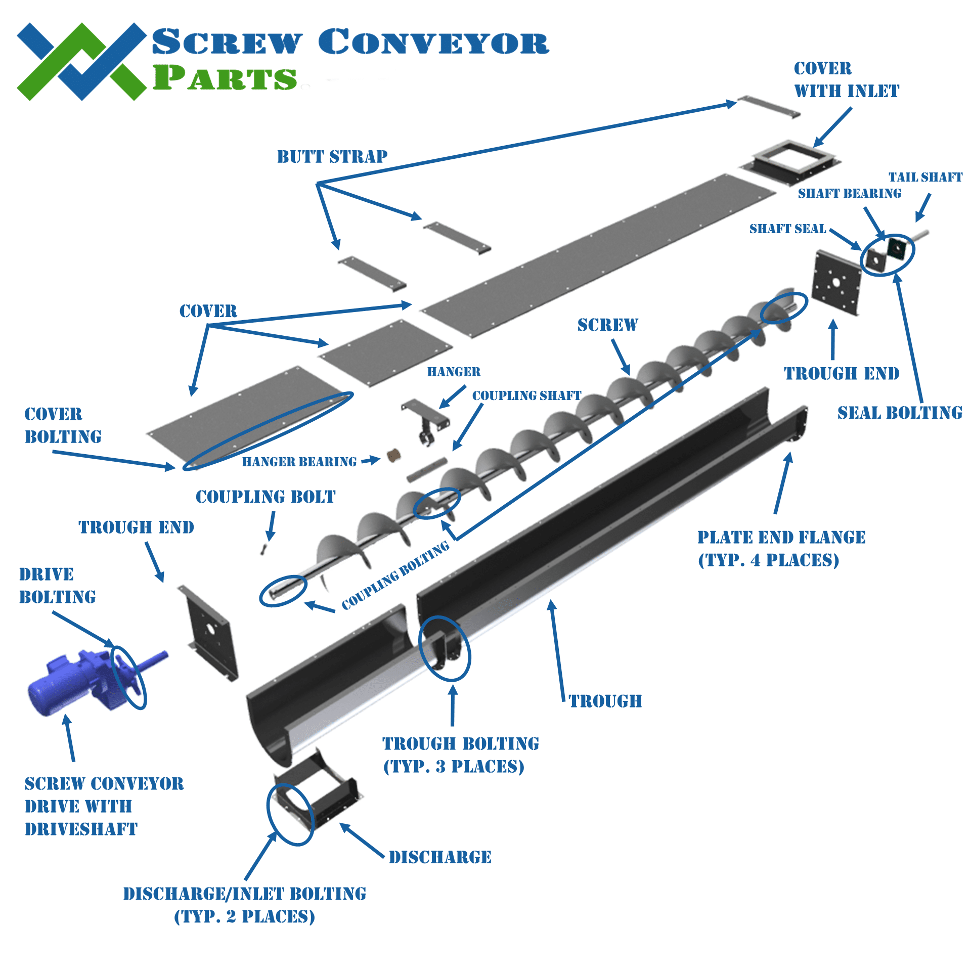
The frac sand blender on the drill site of a modern oil and gas fracking operation is used to blend the proppant with the various chemicals and fluids required to prop open the underground fishers and allow for the extraction of the intended product. At the back of each frac sand blender is a multi-screw conveyor used to elevate and meter the sand from the T-belt to the mixing chamber. These multi-screw conveyors have several specially built screws.
Although every frac sand blender manufacturer builds these screws a little differently, there are a few commonalities that fall outside of the normal requirements of CEMA screws. Below are some of the design requirements of these screws
- 12″ diameter screws
- 2-3 screws per conveyor
- Steeply inclined (45deg+)
- Housing made of pipe
- High speeds (300+ rpm)
- Tight clearances between the screw OD and housing ID.
- 3″ drive shaft and 2 7/16″ tail shaft
- Full pitch
These requirements mean screws built for frac sand blenders have to be specially built for each application and/or they must be tweaked by the installer to get a desired fit. These special requirements create a tough situation for the screw manufacturers and the blender fabricators. Do you buy expensive, purpose built screws costing 2-3 times a standard screw or spend 2-3 times the amount of labor to tweak the standard screw to fit?
A typical challenge experienced by a screw manufacturer is the tight clearance requirement (<1/8″) between the screw OD and housing ID. Many frac sand blender manufacturers want this to be as close as possible. Due to the manufacturing tolerances of the screw and pipe used for the housing obtaining this clearance along the entire length of the screw and from assembly to assembly is nearly impossible without some tweaking by the frac sand blender manufacturer.
An A53 pipe has two controlling mill tolerances, the outside diameter and wall thickness. The outside diameter can vary ± 1% of nominal. The wall thickness can vary +0/-12.5% of nominal. The table below summarizes the allowable variations.
| A53 12″ SCH. 20 Pipe | |
| Outside Diameter | 12.75″ |
| Tolerance | ±1% |
| Upper OD | 12.88″ |
| Lower OD | 12.62″ |
| Wall Thickness | 0.25″ |
| Tolerance | +0/-12.5% |
| Upper Thk | 0.25″ |
| Lower THK | 0.219″ |
| Max. Inside Diameter | 12.44″ |
| Min. Inside Diameter | 12.12″ |
| Ref: ASTM A53/A53M – 12 | |
The overall straightness of the pipe also affects the clearance. A53 pipe has no specifications for straightness. Using ASTM straightness tolerances for mechanical tubing and structural shapes as shown below the following tolerance can be expected.
1/8in x (L/5) = Straightness Tolerance
L = Length in feet
| Pipe Straightness | |
| Pipe Length | 9′-6″ |
| Pipe Straightness Tolerance | 1/2″ Total |
In addition to mill tolerances manufacturing tolerances must be taken into account. Typical tolerances for fabricated sheet metal parts are ±1/8″. The screws had a nominal OD of 12″ with a tolerance of +0/-0.25″. Combining the manufacturing and mill tolerances the theoretical clearances can be seen in the table below.

| Sand Screw Clearance | |
| Pipe Max. Inside Diameter | 12.44″ |
| Pipe Min. Inside Diameter | 12.12″ |
| Screw Nominal OD | 12″ |
| Screw Tolerance | +0/-0.25″ |
| Screw Max. Outside Diameter | 12.00″ |
| Screw Min. Outside Diameter | 11.75″ |
| Allowable Clearances | |
| Max. Theoretical Circ. Clearance | 0.35″ |
| Min. Theoretical Circ. Clearance | 0.06″ |
| Avg. Measured Circ. Clearance | 0.18″ |
On average the circumferential clearance was 0.18″, and varied greatly. Other factors not discussed in detail, but must be considered are the allowable screw straightness, concentricity of the screw in the housing, and the effects on mill tolerances when welding on the pipe. All of these contribute to uneven gaps causing small gaps on one side, while allowing large gaps on the other.
When the mill and manufacturing tolerances are considered it is easy to see why the specified circumferential clearance of 1/8″ was not achievable at every point along the unit. Acceptable variations due to manufacturing and mill tolerances in screw OD, pipe wall thickness, pipe OD and straightness are all contributing factors to the variations witnessed with the final product. With an allowable circumferential clearance of 0.06″ to 0.35″ based on mill and manufacturing tolerances the measured average clearance of 0.18″ is within this acceptable range.